46 Results
View results:
Sort by:

You can use the selection options in the printout report to receive the detail results (in short or long form) to illustrate the individual buckling modes with the relevant buckling analysis.

In CRANEWAY, the action of a rail as "statically effective" or "statically ineffective" is defined under "Rail‑Flange Connection" in the Details dialog box. This setting controls the calculation of the load introduction length according to EN 1993-6, Tab. 5.1.

The RF‑/STEEL EC3 add-on module can perform the design of fillet welds for all parametric, welded cross-sections of the cross-section library. For this, the option must be activated in the detail settings of the module. As an alternative, you can also use a surface model for the design.

Structure stability is not a new phenomenon when referring to steel design. The Canadian steel design standard CSA S16 and the most recent 2019 release are no exception. Detailed stability requirements can be addressed with either the Simplified Stability Analysis Method in Clause 8.4.3 or, new to the 2019 standard, the Stability Effects in Elastic Analysis method provided in Annex O.
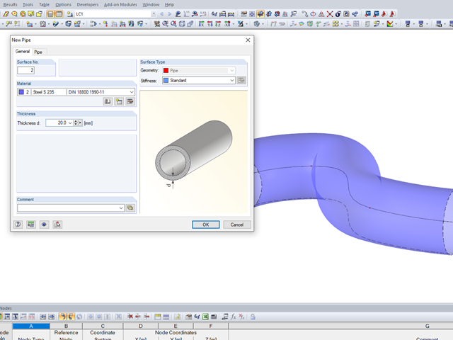
It may become necessary to analyze pipe cross‑sections as surface models in plant engineering in particular, but also when analyzing details of structural systems. For this purpose, RFEM offers the option to create pipe cross‑sections automatically by means of a line.

For the design of concrete surfaces, the rib component of the internal forces can be neglected for the ULS calculation and for the analytical method of the SLS calculation, because this component is already considered in the member design. To do this, select the check box in the "Details" dialog box. If no rib was defined, this function is not available.
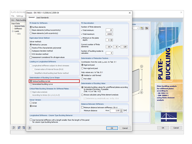
In PLATE‑BUCKLING 8, two options in the detail settings can be used to calculate the reduction factors of plate buckling.

In RF-/FOUNDATION Pro, a graphical display of the result details is available. To see them, go to Window 2.2 Governing Design Criteria after the calculation. In the interactive graphic of this window, individual design-relevant values can be displayed for each design performed.
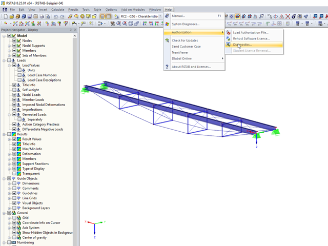
In RFEM 5 and RSTAB 8, you can view detailed information on the currently used license and installed dongle driver. In case of any problems with the license, you can send the created text file to the Dlubal Software hotline, which allows us to provide you with a fast and efficient analysis. To create the file, select "Help" → "Authorization" → "Diagnostics".
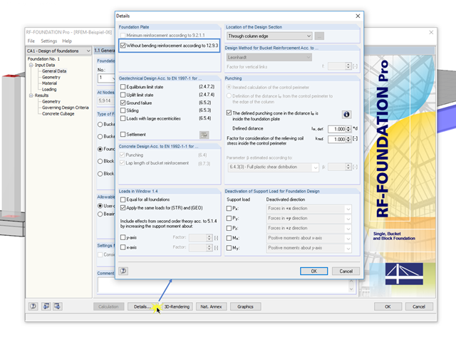
In RF-/FOUNDATION Pro, you can also calculate unreinforced foundation plates according to Section 12.9.3 of EN 1992-1-1 [1]. To do this, select the "Without bending reinforcement according to 12.9.3" check box in the "Foundation Plate" section of the "Details" dialog box.
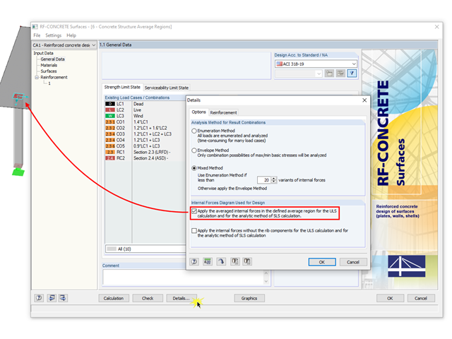
The averaged internal forces from the previously defined average regions can also be used for designing concrete surfaces. To do this, click [Details] in RF‑CONCRETE Surfaces, then select the corresponding check box. This function is accessible only if you previously defined an average region.
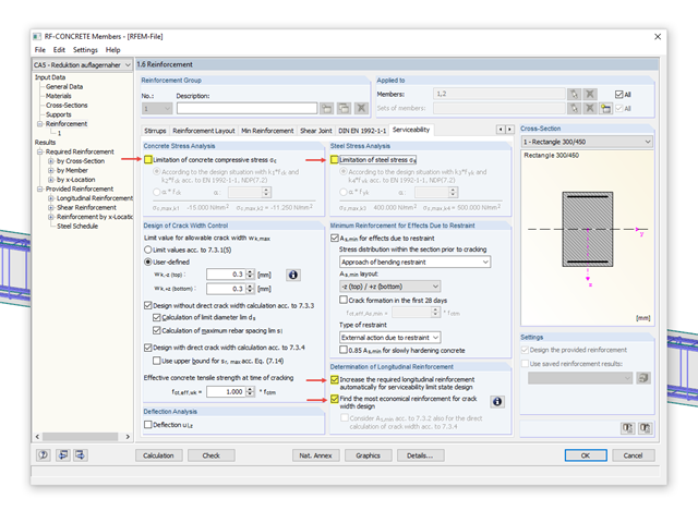
In Part 1, the selection of the design criteria for dimensioning the reinforcement for the serviceability limit state design in RF‑CONCRETE Members and CONCRETE was explained. Now, we go into detail for the function "Find economical reinforcement for crack width design".

When defining the effective slab width of T-beams, RFEM provides the predefined widths that are determined as 1/6 and 1/8 of the member length. A more detailed explanation on these two factors is given below.

The design of cold-rolled steel products is defined in EN 1993-1-3. Typical cross-section shapes are channel, C, Z, top hat, and sigma sections. These are cold-rolled steel products made of thin-walled sheet metal that has been cold-formed by roll-forming or bending methods. When designing the ultimate limit states, it is also necessary to ensure that local transverse forces do not lead to compression, crippling of the web, or local buckling in the web of the sections. These effects can be caused by local transverse forces by the flange into the web, as well as by support forces at the supported points. Section 6.1.7 of EN 1993-1-3 specifies in detail how to determine the resistance of the web Rw,Rd under local transverse forces.
Due to the special properties of glass, you also have to pay close attention to the details when modeling in an FE model. Glass has a very high compressive strength and is, therefore, generally only designed for its tensile stresses. One particular disadvantage of the material is its brittleness. Stress peaks that occur in the calculation must, therefore, not be readily neglected.
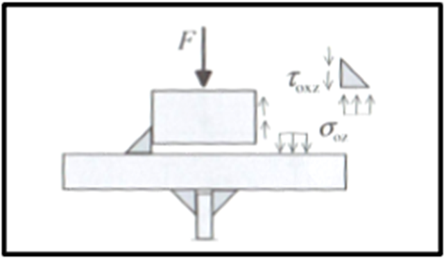
The definition of the non-linear contact problem plays an important role for more detailed investigations of shear/hole bearing connections or their immediate environment. This article uses a solid model to search for comparable and simplified surface models.

RFEM and RSTAB offer different options to model bored piles. One option is to display bored piles as single-valued supports or hinged columns. Another option is realistic modeling while taking the soil into account by means of applying a member elastic foundation. The two following examples will describe it in detail. However, pile base resistance, skin friction, and soil layers are not considered in this technical article.

When designing steel columns or steel beams, it is usually necessary to carry out cross-section design and stability analysis. While the cross-section design can usually be performed without giving further details, the stability analysis requires further user-defined entries. To a certain extent, the member is cut out of the structure; therefore, the support conditions have to be specified. This is particularly important when determining the ideal elastic critical moment Mcr. Furthermore, it is necessary to define the correct effective lengths Lcr. These are required for the internal calculation of slenderness ratios.
Daniel Dlubal's bachelor's thesis focuses on presenting and highlighting the chances, advantages, and opportunities of BIM when performing the structural analysis and design of buildings. The essential information of a structural analysis is shown and the data exchange between the CAD and the structural engineering software is explained in detail as well.
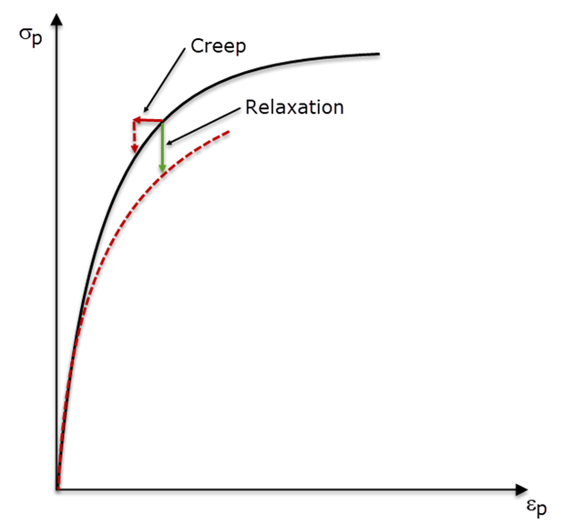
The time-dependent stress losses from creeping, shrinkage, and relaxation have to be considered when designing prestressed concrete components. The consideration of relaxation losses when designing prestressed concrete in RF-TENDON and RF-TENDON Design is discussed in detail in the following text.
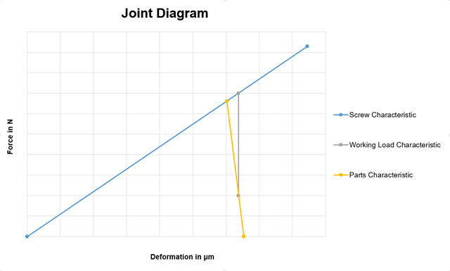
When modeling surface models, such as a frame joint or similar structures, there is always the question of how to model a prestressed bolt connection. In this case, it is always necessary to find a compromise between the practicable and detailed solution. The following article describes the modeling procedure of such a connection, based on the joint diagram calculation method.
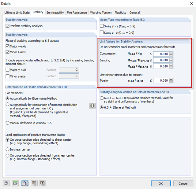
As of the program version X.11, the filter options of small compression forces or moments for stability analysis in RF‑/STEEL EC3 have been revised. The revision of these filter options in the "Stability" tab of the "Details" dialog box allows you to work in the module transparently, since they are now independent of the design.
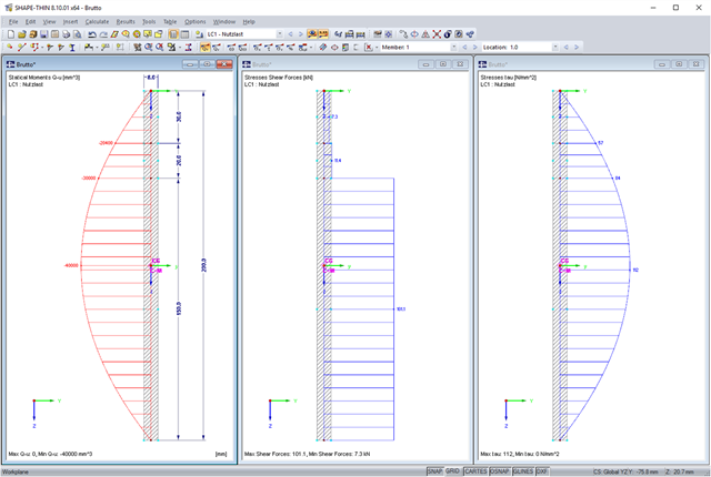
SHAPE-THIN allows you to calculate section properties and stresses of any cross-sections. If a flange or a web is weakened by bolt holes, you can consider this by using null elements. The stresses are subsequently recalculated with the reduced cross-section values. In this case, it is necessary to pay a special attention to shear stresses. By default, these are set to zero in the area of the null elements. When recalculating shear stresses with the reduced cross-section values and without further adaptation, it turns out that the integral of the shear stresses is no longer equal to the applied shear force. The following example shows in detail how to calculate the shear stress.
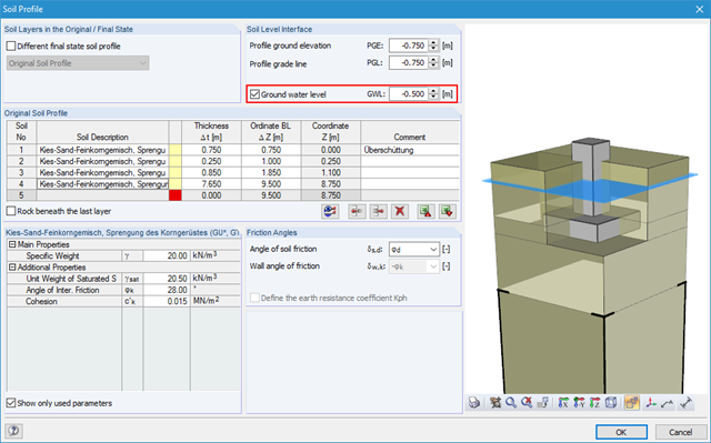
Using RF-/FOUNDATION Pro, it is possible to perform geotechnical design according to EN 1997‑1 [1] for single foundations. Subsequently, the program displays detailed information about the influence of the ground water level on the selected design according to EN 1997‑1.
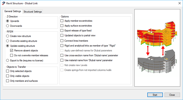
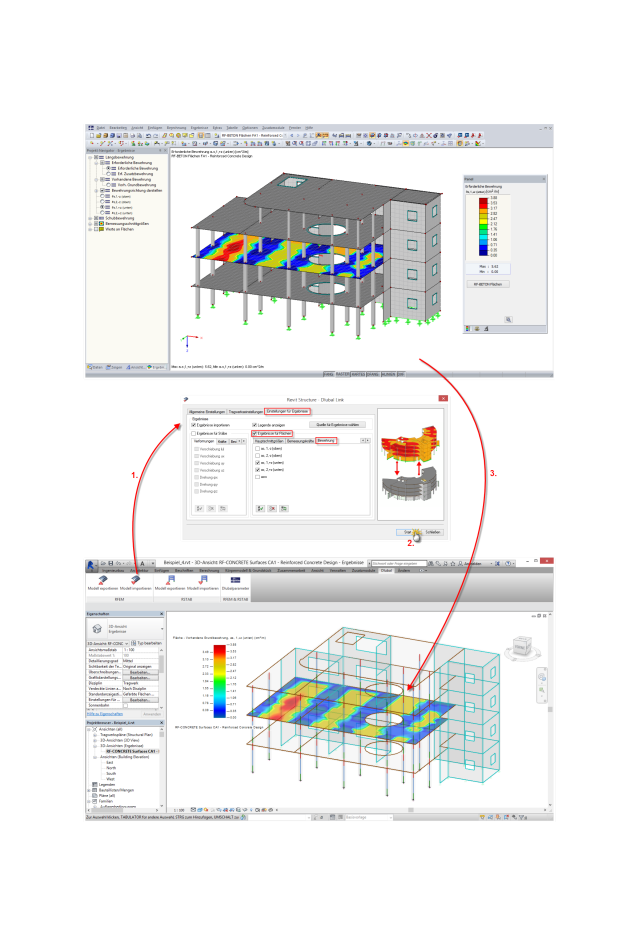
BIM is often used when it comes to data management in civil engineering. The individual disciplines of architecture, structural design, construction, and structural monitoring are coming closer together. Building Information Modeling makes this possible.. Dlubal Software provides a wide range of formats for data exchange. The following article explains the details of the interface with Autodesk Revit and, in particular, the export settings.
Based on the technical article about the ultimate limit state design of rail welds, the following explanation refers to the process of fatigue design of rail welds. In particular, this article explains in detail the effects of considering an eccentric wheel load of 1/4 of the rail head width.
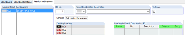
RFEM and RSTAB provides two different methods for the superposition of load cases. Using load combinations, the loads of individual load cases are superimposed and calculated in a "big load case". On the other hand, result combinations only combine the results of the individual load cases. This article describes the with the basis of defining result combinations and explain it in detail on two examples.
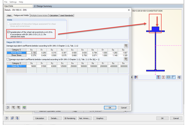
The eccentric wheel load application of 1/4 of the rail head width has to be considered only for fatigue design from damage class S3 according to DIN EN 1993‑6. An additional input option in detail settings allows you to consider this eccentricity for fatigue design at the ultimate limit state as well. By selecting this option, the design with the eccentric load applied is always considered without regard to the damage class.
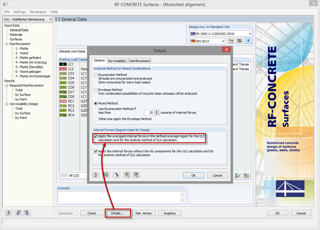
In order to use internal forces from average regions also for the design of concrete surfaces, you have to activate them in the module. For this, click the [Details] button in the "Tools" tab and select the option "Apply the averaged internal forces in the defined average region for the ULS calculation and for the analytic method of SLS calculation."
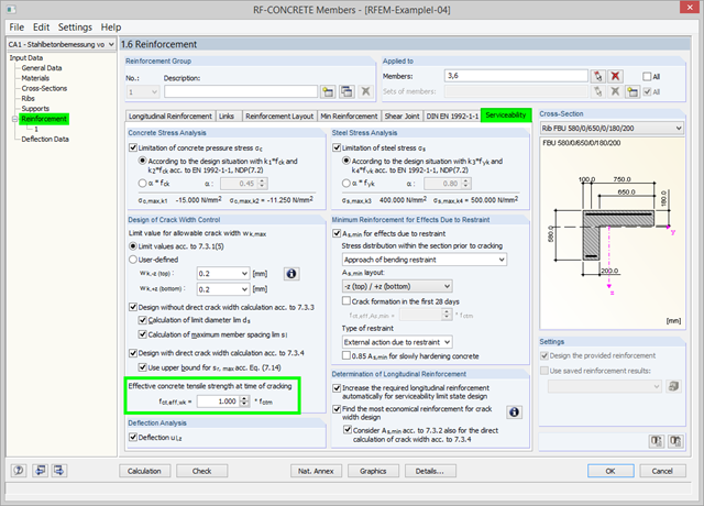
As of program version 5.06, you can use the option to adjust the effective concrete tensile strength fct,eff,wk at the time of cracking. At the start of the SLS design, the program checks whether the internal forces can cause cracks in the concrete. For this, the effective concrete tensile strength at the time of cracking is applied. You can adjust the strength via the factor. The calculation details display the adjusted value.